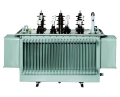
Amorphous alloy transformer, the principle is the same as the sealed transformer. The core uses amorphous alloy strip, amorphous alloy material does not have crystal structure, small magnetization power, high resistivity, is 3-6 times of ordinary silicon steel sheet, so the eddy current loss is small, with this material as the core, no-load loss on the basis of GB/T6451 standard down 60%, is a new type of energy-saving transformer, With the characteristics of environmental protection, high efficiency, energy saving, low loss and anti-interference, it is an ideal product for the replacement of distribution network.
Product/performance characteristics
Amorphous alloy transformer core magnetic material using amorphous alloy strip, its most prominent feature is the no-load current and no-load loss is very small.
The transformer iron core is made of amorphous alloy strip generally rolled into a three-phase five-column structure, so that not only the height of the transformer is lower than that of the three-phase three-column type, but also the two side yokes can flow in the high order harmonic or zero sequence component of the magnetic flux, effectively reducing the leakage voltage drop and improving the current quality.
Low voltage winding in addition to small capacity (100kVA below) using copper wire, generally use copper foil wound cylinder structure; The high voltage winding adopts multi-layer cylinder structure, the ampere-turns distribution of the winding is balanced, and the magnetic leakage is small. The high and low voltage coils are wound together with a wire tension device and are hot-pressed to enhance mechanical strength and resistance to short circuit impact.
The body adopts no hanging core structure, and adopts vacuum drying and vacuum oil injection technology. The oil tank is a fully sealed oil tank without oil storage tank.
Because the product adopts a fully sealed structure, the insulating oil and insulating medium do not contact with the air, and there is no need to change the oil under normal operation, which greatly reduces the maintenance cost of the transformer and extends the service life.
Through the calculation of annual power loss, annual power loss cost, and annual saving electricity, it is generally possible to recover its increased investment cost relative to the silicon steel sheet core transformer within three years.
Overload capacity/technical parameters
SH15-M-30 ~ 2500/6-10 amorphous alloy non-excited distribution transformer
|
Transformer Capacity (kVA) |
High voltage (kV) |
High pressure tap range (%) |
Low voltage (kV) |
Join group label |
No-load loss |
load |
No-load current (%) |
short circuit impedance |
|
30 |
|
|
|
|
33 |
630/600 |
1.5 |
4.0 |
|
50 |
|
|
|
|
43 |
910/870 |
1.2 |
|
|
63 |
|
|
|
|
50 |
1090/1040 |
1.1 |
|
|
80 |
|
|
|
|
60 |
1310/1250 |
1.0 |
|
|
100 |
|
|
|
|
75 |
1580/1500 |
0.9 |
|
|
125 |
|
|
|
|
85 |
1890/1800 |
0.8 |
|
|
160 |
|
|
|
100 |
2310/2200 |
0.6 |
||
|
200 |
6 |
|
|
120 |
2730/2600 |
0.6 |
||
|
250 |
6.3 |
土 5 |
|
|
140 |
3200/3050 |
0.6 |
|
|
315 |
10 |
|
0.4 |
Dyn11 |
170 |
3830/3650 |
0.5 |
|
|
400 |
10.5 |
±2x2.5 |
|
|
200 |
4520/4300 |
0.5 |
|
|
500 |
11 |
|
|
|
240 |
5410/5150 |
0.5 |
|
|
630 |
|
|
|
|
320 |
6200 |
0.3 |
|
|
800 |
|
|
|
|
380 |
7500 |
0.3 |
|
|
1000 |
|
|
|
|
450 |
10300 |
0.3 |
4.5 |
|
1250 |
|
|
|
|
530 |
12000 |
0.2 |
|
|
1600 |
|
|
|
|
630 |
14500 |
0.2 |
|
|
2000 |
|
|
|
|
750 |
18300 |
0.2 |
|
|
2500 |
|
|
|
|
900 |
21200 |
0.2 |
5 |
SH16-M-30~2500/6~10 amorphous alloy non-excited distribution transformer
|
Transformer Capacity (kVA) |
High voltage (kV) |
High pressure tap range (%) |
Low voltage (kV) |
Join group label |
No-load loss |
load |
No-load current (%) |
short circuit impedance |
|
30 |
|
|
|
|
33 |
565/540 |
1.5 |
4.0 |
|
50 |
|
|
|
|
43 |
820/785 |
1.2 |
|
|
63 |
|
|
|
|
50 |
980/935 |
1.1 |
|
|
80 |
|
|
|
|
60 |
1180/1120 |
1.0 |
|
|
100 |
|
|
|
|
75 |
1420/1350 |
0.9 |
|
|
125 |
|
|
|
|
85 |
1700/1820 |
0.8 |
|
|
160 |
|
|
|
100 |
2080/1980 |
0.6 |
||
|
200 |
6 |
|
|
120 |
2450/2340 |
0.6 |
||
|
250 |
6.3 |
土 5 |
|
|
140 |
2880/2740 |
0.6 |
|
|
315 |
10 |
|
0.4 |
Dyn11 |
170 |
3400/3280 |
0.5 |
|
|
400 |
10.5 |
±2x2.5 |
|
|
200 |
4070/3870 |
0.5 |
|
|
500 |
11 |
|
|
|
240 |
4870/4630 |
0.5 |
|
|
630 |
|
|
|
|
320 |
5580 |
0.3 |
|
|
800 |
|
|
|
|
380 |
6750 |
0.3 |
|
|
1000 |
|
|
|
|
450 |
9270 |
0.3 |
4.5 |
|
1250 |
|
|
|
|
530 |
10800 |
0.2 |
|
|
1600 |
|
|
|
|
630 |
13000 |
0.2 |
|
|
2000 |
|
|
|
|
750 |
16400 |
0.2 |
|
|
2500 |
|
|
|
|
900 |
19000 |
0.2 |
5 |